Wolfram Language Paclet Repository

Community-contributed installable additions to the Wolfram Language

Primary Navigation

    • Cloud & Deployment
    • Core Language & Structure
    • Data Manipulation & Analysis
    • Engineering Data & Computation
    • External Interfaces & Connections
    • Financial Data & Computation
    • Geographic Data & Computation
    • Geometry
    • Graphs & Networks
    • Higher Mathematical Computation
    • Images
    • Knowledge Representation & Natural Language
    • Machine Learning
    • Notebook Documents & Presentation
    • Scientific and Medical Data & Computation
    • Social, Cultural & Linguistic Data
    • Strings & Text
    • Symbolic & Numeric Computation
    • System Operation & Setup
    • Time-Related Computation
    • User Interface Construction
    • Visualization & Graphics
    • Random Paclet
    • Alphabetical List
  • Using Paclets
    • Get Started
    • Download Definition Notebook
  • Learn More about Wolfram Language

Q3mini

Guides

  • Fermionic Quantum Computation
  • Q3: Symbolic Quantum Simulation
  • Quantum Information Systems
  • Quantum Many-Body Systems
  • Quantum Spin Systems

Tech Notes

  • About Q3
  • Q3: Quick Start
  • Quantum Fourier Transform
  • Quantum Information Systems with Q3
  • Quantum Many-Body Systems with Q3
  • Quantum Operations
  • Quantum Spin Systems with Q3
  • Quantum States
  • Quantum Teleportation
  • Quick Quantum Computing with Q3

Symbols

  • Basis
  • Boson
  • Bra
  • CNOT
  • ControlledGate
  • ExpressionFor
  • Fermion
  • Heisenberg
  • Ket
  • Let
  • Majorana
  • Matrix
  • Multiply
  • NambuGreen
  • NambuHermitian
  • NambuMatrix
  • NambuUnitary
  • Pauli
  • Phase
  • QuantumCircuit
  • Qubit
  • Qudit
  • RandomWickCircuitSimulate
  • Rotation
  • Species
  • Spin
  • SWAP
  • WickCircuit
  • WickEntanglementEntropy
  • WickEntropy
  • WickGreenFunction
  • WickJump
  • WickLindbladSolve
  • WickLogarithmicNegativity
  • WickMeasurement
  • WickMonitor
  • WickMutualInformation
  • WickNonunitary
  • WickSimulate
  • WickState
  • WickUnitary

Overviews

  • The Postulates of Quantum Mechanics
  • Quantum Algorithms
  • Quantum Computation: Models
  • Quantum Computation: Overview
  • Quantum Error-Correction Codes
  • Quantum Information Theory
  • Quantum Noise and Decoherence
Quantum Fourier Transform
Definition
Quantum Implementation
Physical Meaning
Semiclassical Implementation
The quantum Fourier transform is a unitary transformation of quantum states. It is analogous to the discrete Fourier transform of a finite set of numbers. In the case of the quantum Fourier transform, the numbers are replaced with quantum states.
The quantum Fourier transform can be performed efficiently on a quantum computer consisting of
n
qubits with only
O(
2
n
)
elementary quantum gate operations, compared to
O(n
n
2
) gates for the best known classical algorithm for a discrete Fourier transform. This exponential speedup in the quantum Fourier transform algorithm relative to the classical counterpart enabled the celebrated quantum factorization algorithm to achieve a similar efficiency.
Apart from the above mentioned quantum factorization algorithm, the quantum Fourier transformation is a key part of many other quantum algorithms, such as the quantum phase estimation, the order-finding problem, the discrete logarithm, and most importantly the hidden subgroup problem. Such a wide range of applications of the quantum Fourier transform stems from the fact that all known quantum algorithms featuring an exponential speedup over classical algorithms are variations of the hidden subgroup problem and, as first realized by Kitaev (1996), the key step to solve the latter problem is the quantum Fourier transform.
See also Section 4.3 of the
Quantum Workbook (2022)
.
QFT
Represents the quantum Fourier transform
ControlledPower
Represents a controlled-power of unitary operator
ControlledGate
Represents a controlled-unitary gate
Q3 functions related to the quantum Fourier transform.
Make sure that the Q3 framework is loaded to use the demonstrations in this document.
In[1]:=
Needs["QuantumMob`Q3`"]
Definition
To make the physical meaning underlying the quantum Fourier transform clearer, in this document, we use a slightly different notation for the computational basis states, and denote them by
|
X
x
〉:=|
x
1
〉⊗|
x
2
〉⊗⋯⊗|
x
n
〉
for
x=0,1,2,…,
n
2
-1
, where
x
k
for
k=1,2,…,n
are the binary digits of
x=
(
x
1
x
2
⋯x
n
)
2
.
The quantum Fourier transform, QFT for short, is a unitary transformation defined by the association
U
QFT
|
X
y
〉:=
1
n/2
2
n
2
-1
Σ
x=0
|
X
x
〉
x
p
y

for
y=0,1,2,…,
n
2
-1
, where
p
y
is the
th
y
“wave number” defined by
p
y
:=
2πy
n
2
=2
π(0.
y
1
y
2
⋯y
n
)
2
.
Like
x
k
,
y
k
for
k=1,2,…,n
are the binary digits of
y=
(
y
1
y
2
⋯y
n
)
2
.
The expression on the right-hand side of the above definition is of a familiar form of the discrete Fourier transform except that instead of numerical coefficients for the exponential factor
x
p
y

, there appear state vectors. Therefore, one may think of the quantum Fourier transform as a vector-valued discrete Fourier transformation.
Physical Meaning
In many physical applications, there is a more important aspect of the quantum Fourier transform than its formal similarity to the discrete Fourier transform. It is useful and inspiring to regard the QFT as a basis change, a unitary transformation from the computational basis
{|
X
x
〉:x=0,1,2,…,
n
2
-1}
to the so-called “conjugate basis”

P
y
:=
U
QFT

X
y
:y=0,1,2,…,
n
2
-1
.
The key observation is that in the “continuum” limit (
L:=
n
2
→∞
), the computational basis corresponds to the eigenbasis of the “position” and the conjugate basis to that of the “momentum”. Indeed, one can see that the two observables
X:=
Σ
x
|
X
x
〉x〈
X
x
|
and
P:=
Σ
y
|
P
y
〉
p
y
〈
P
y
|
bearing eigenvalues
x
and
p
y
, respectively, satisfy the relation
-aP

X
+aP

=X-aI
.
This implies that
-aP

is a translation operator, and
P
is the generator of the translation, i.e., the momentum.
This notion can be made rigorous even in a finite-dimensional Hilbert space using the unitary operators
exp(-pX)
and
exp(-aP)
, which generate the so-called Weyl-Heisenberg group; see Weyl (1931, Section IV.14) for example.
The quantum Fourier transform appears frequently in many quantum algorithms (notably the quantum phase estimation algorithm), in an explicit or disguised form. The relation between the computational and conjugate basis defined above is useful to understand the principle behind the particular algorithms.
Quantum Implementation
The quantum Fourier transform algorithm is to efficiently implement the unitary operator
U
QFT
in terms of the elementary gates. Getting back to the definition, the quantum Fourier transform maps the quantum states by
U
QFT
|
X
y
〉:=
1
n/2
2
n
2
-1
Σ
x=0
|
X
x
〉
x
p
y

with wave number
p
y
:=
2πy
n
2
for
y=0,1,2,…,
n
2
-1
.
Since the characteristic properties of the Fourier transform of any kind are attributed to an oscillatory phase factor
x
p
y

, we start by elaborating it. The product
x
p
y
in the exponent is given by
x
p
y
=
2πxy
n
2
=2
π(0.
x
1
x
2
⋯x
n
)
2
y=2πy
n
Σ
k=1
x
k
-k
2
,
which recasts the phase factor into the form
exp(x
p
y
)=
n
Π
k=1
exp2πy
x
k
-k
2

.
We put it back in the defining expression of quantum Fourier transform in the above, and rewrite the sum over
x
with the sum over bit values
x
k
∈{0,1}
, which lead to
U
QFT
|
X
y
〉=
n
⊗
k=1
Σ
x
k
=0,1
|
x
k
〉
2π
x
k
y
k
2

.
For a fixed
k
, the ratio
y
k
2
is represented in binary digits as
y
k
2
=
(
y
1
y
2
⋯y
n-k
.
y
n-k+1
⋯y
n-1
y
n
)
2
.
The integer part does not affect the sum because
2πm

=1
for any integer
m
; only the fractional part
(0.
y
n-k+1
⋯y
n
)
2
does. Depriving the phase factors

x
k
p
y

of the integer parts, we arrive at the expression for the result of the transformation
U
QFT
|
X
y
〉=
n
⊗
k=1
Σ
x
k
=0,1
|
x
k
〉
2π
x
k
(0.
y
n-k+1
⋯y
n-1
y
n
)
2

.
Explicitly writing the sums over bit values
x
k
, it reads as
U
QFT
|
X
y
〉=
|0〉+|1〉
2π0.
y
n

2
⊗
|0〉+|1〉
2π0.
y
n-1
y
n

2
⊗⋯⊗
|0〉+|1〉
2π0.
y
1
y
2
⋯y
n

2
.
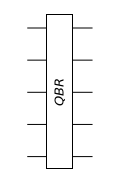
Interestingly, the state resulting from the quantum Fourier transform is clearly a product state. The first factor is stored in the first qubit of the quantum register, and consecutive factors are stored in the corresponding qubits in the same order. For later analysis, it is useful to reverse the order. This is equivalent to performing the quantum bit-reversal transform (
QBR
)
U
QBR
|
y
1
〉⊗|
y
2
〉⊗⋯⊗|
y
n
〉=|
y
n
〉⊗⋯⊗|
y
2
〉⊗|
y
1
〉
.
Note that the quantum bit-reversal transform can be efficiently implemented by a sequence of SWAP gates as in Figure 1. Applying the quantum bit-reversal transform after the quantum Fourier transform, we arrive at the final expression that we analyze subsequently
U
QBR
U
QFT
|
X
y
〉=
|0〉+|1〉
2π0.
y
1
y
2
…y
n

2
⊗⋯⊗
|0〉+|1〉
2π0.
y
n-1
y
n

2
⊗
|0〉+|1〉
2π0.
y
n

2
.
=
Figure 1. An implementation of quantum bit-reversal transform (QBR).
So far, we have done nothing but re-express the defining equation of the quantum Fourier transform. Now, we identify the elementary quantum logic gates that compose the transform. The product form in the above is remarkably simple to analyze. In particular, the state stored in the last qubit depends only on its own state
|
y
n
〉
, and the relative phase factor
2π
(0.
y
n
)
2

is equivalent to applying the Hadamard gate,
|0〉+|1〉
2π
(0.
y
n
)
2

2
=
|0〉+
y
n
|1〉(-1)
2
=H|
y
n
〉
.
The second last factor depends not only on the input state
|
y
n-1
〉
of the second last qubit but also on the last qubit. However, the phase factor
2π
(0.
y
n-1
)
2

governed by
|
y
n-1
〉
is again equivalent to the Hadamard gate. On the other hand, the additional phase factor
2π
(0.0
y
n
)
2

=
y
n

2π/
2
2


is equivalent to operating the
controlled-
Z
2
gate, where
Z
k
:=
1
0
0
2π
k
2

,
conditioned on the input state
|
y
n
〉
of the last qubit. In short, the state stored in the second last qubit is given by
|0〉+|1〉
2π
(0.
y
n-1
y
n
)
2

2
⊗|
y
n
〉=
y
n
Z
2
H
y
n-1
⊗|
y
n
〉
.
More generally, the state on the
th
k
qubit
|0〉+|1〉
2π
(0.
y
k
y
k+1
⋯y
n
)
2

2
is characterized by the relative phase angle
This is depicted by the quantum circuit in Figure 2.
Figure 3. A quantum circuit for the quantum Fourier transform.

Computational Complexity

Demonstration

Here, we simulate the quantum Fourier transform on a quantum register of 4 qubits.
Take a quantum register.
Define the QFT operator.
For a reference, consider the quantum Fourier transform as a block unitary gate.
Now, construct the quantum circuit implementing the quantum Fourier transform.
Further expand each of the controlled-power gate.
To verify the above quantum circuit model, compare its matrix representation with the matrix for the discrete Fourier transform.
Semiclassical Implementation
The semiclassical implementation is not only interesting from a physical point of view, but it is also extremely interesting given the current level of technology (Griffiths & Niu, 1996). Since it does not require any entanglement, a quantum information resource that is the most fragile and hence difficult to maintain, many experiments are using this implementation whenever the QFT and/or the quantum phase estimation is in need (Chiaverini, 2005; Higgins et al., 2007).
which follows directly from the orthogonality relation
This expression for the inverse quantum Fourier transform suggests that the inverse quantum Fourier transform is just another form of the quantum Fourier transform, and indeed, this is a characteristic property common to any kind of Fourier transform. This implies that one can recover the original quantum Fourier transform from the inverse quantum Fourier transform, and vice versa, in several ways.
Figure 6. A quantum circuit equivalent to that in Figure 5, but with measurements displayed explicitly.
According to the principle of deferred measurement, the measurement can be performed before the controlled unitary gates as in Figure 7.
Figure 7. A quantum circuit to implement quantum Fourier transform semiclassically. Note that the classical bit string from measurement outcomes needs to be reversed.
This form is exactly the quantum circuit derived in Griffiths & Niu (1996). The important point is that after the measurement, the controlled-unitary gates become just classical feedback controls that require no entanglement.

Demonstration

Here, we simulate the semiclassical implementation of the quantum Fourier transform. Again, we consider a quantum register of four qubits.
Using the relation between the quantum Fourier transform and its inverse, one can construct another equivalent quantum circuit as follows. Here, the tilde accent emphasizes that the control qubits are in the reversed order.
Expand each of the controlled-power gates.
Verify the above quantum circuit model by comparing its matrix representation with the matrix for the discrete Fourier transform.
Pick an input state randomly from the computational basis, and include the measurements as well.
Convert the above quantum circuit to the form that is suitable for the semiclassical implementation of the quantum Fourier transform.
To verify the equivalence of the two quantum circuit models, we compare the probability distributions.
Note that the bit strings of the measurement outcomes from the semiclassical model must be reversed .
The discrepancy between the two distributions is due to the finite sample size.
Another way to test the equivalence of the fully quantum and semiclassical implementation of the quantum Fourier transform is to randomly take an input state that ends up in a product state.
Again, recall that the order of qubits are reversed in the semiclassical implementation.

© 2025 Wolfram. All rights reserved.

  • Legal & Privacy Policy
  • Contact Us
  • WolframAlpha.com
  • WolframCloud.com