Basic Examples (7)
Annotate a graphical object with an underbrace:
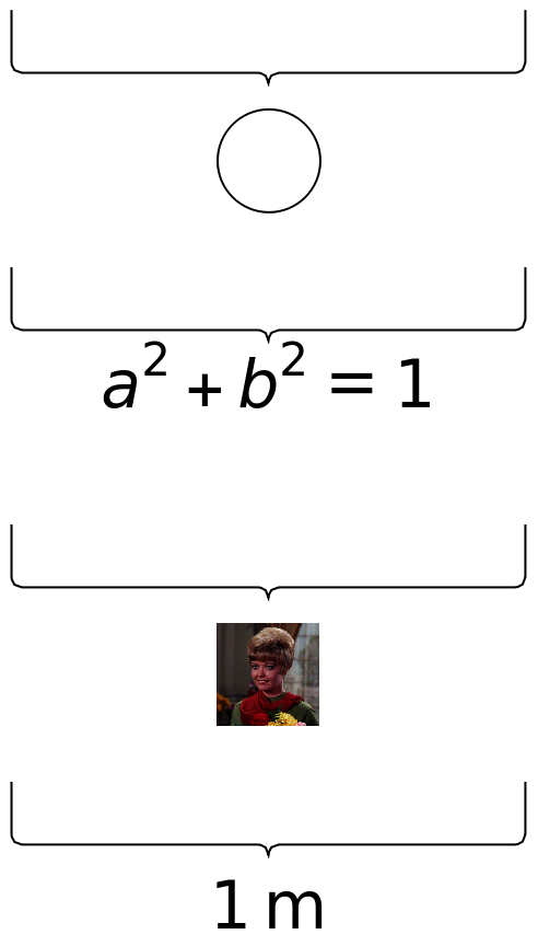
Use multiple annotations:
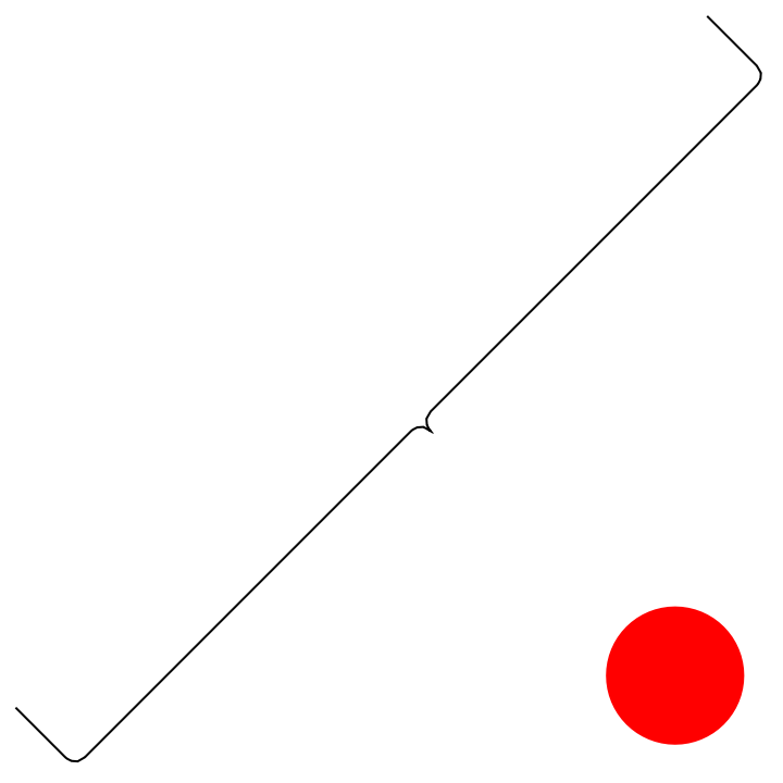
By swapping the order of the two anchor points, create an overbrace:
Adjust the position and rotation of the label:
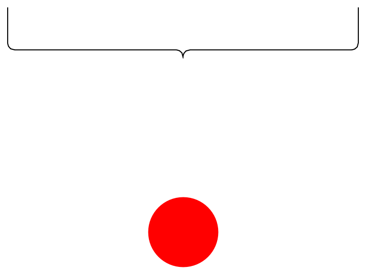
By default, the brace automatically adjusts its rotation to the annotated object:
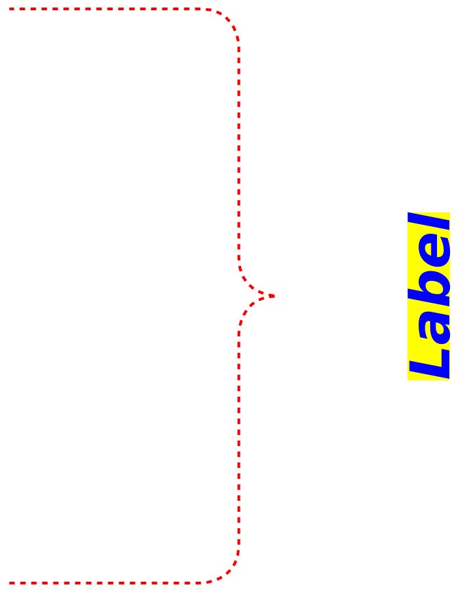
Style the labels as well as the curves:
Use Point objects directly as anchor points:
Scope (10)
Label content (2)
Use the underbrace with no label:
The label does not have to be text:
Label position (3)
Position the label further from the cusp:
The offset is taken in the direction of the cusp:
The textual label can be offset in the horizontal and vertical directions using an additional argument:
Any specification that is valid for the third argument of Text is also allowed. Here, an Offset is used:
Specify the relative position of the label with respect to the edges:
Curve dimensions (2)
Make the edges longer:
Specify the relative position of the cusp with respect to the edges:
Presentation (3)
Choose different colors, thicknesses, etc. for the curve:
Choose different styles for the label:
Style both the curve and the label:
Options (8)
Direction (3)
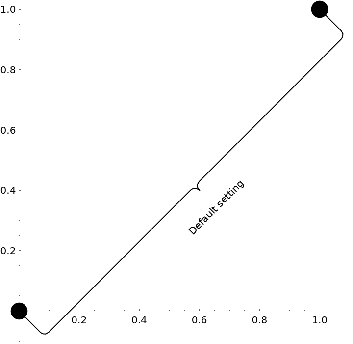
By default, the curve stretches between the two anchor points:
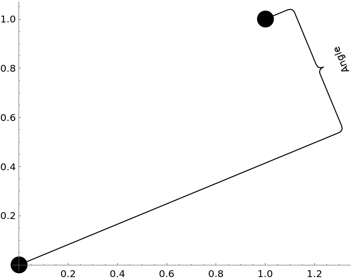
Specify explicitly the direction of the edges:
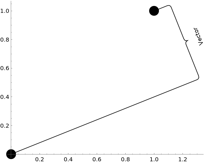
The direction can also be specified as a vector:
RotateLabel (3)
The label is by default parallel to the brace:
Disable rotation:
The angle can also be given explicitly:
The combination of both approaches yields an automatically rotated label with the explicitly given rotation offset:
RoundingRadius (2)
Adjust the radius of the joints:
The radius of the cusp and outer joints can be specified independently:
Applications (2)
Make a technical drawing with proper physical units:
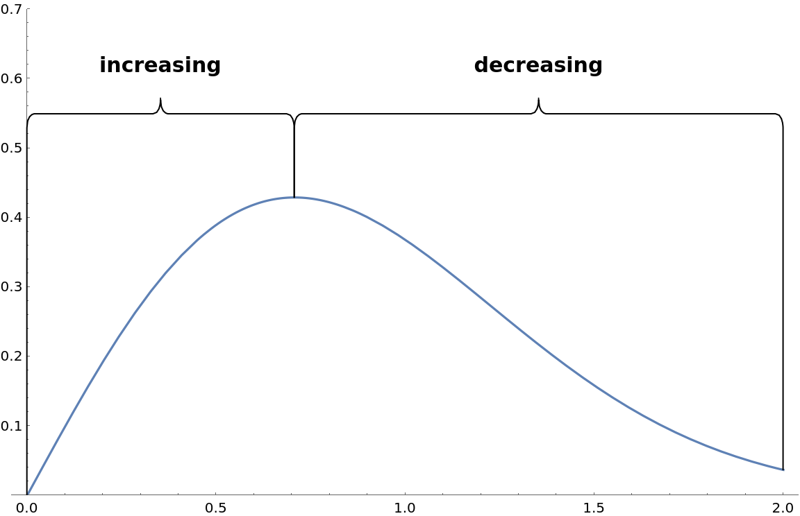
Describe the regions where a given function is monotonically increasing and decreasing:
Properties and Relations (1)
GraphicsBrace can be used in Graphics the way that an underbrace is used in text:
Possible Issues (5)
When the first argument is to be taken as a literal, wrap it in Inset:
When the other arguments are not numeric, no evaluation of GraphicsBrace takes place:
The label may be set too close to the cusp:
Position the label further from the cusp:
When the line segments are too small with respect to the rounding radii, undesired behavior occurs:
To prevent this, adjust the rounding radii appropriately:
For an overbrace, the label is upside down:
Turn off the automatic rotation of the label:
Neat Examples (2)
Use the brace as a graphics primitive for artistic drawing:
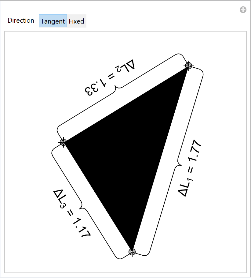
Annotate the side lengths of a dynamically changing triangle:

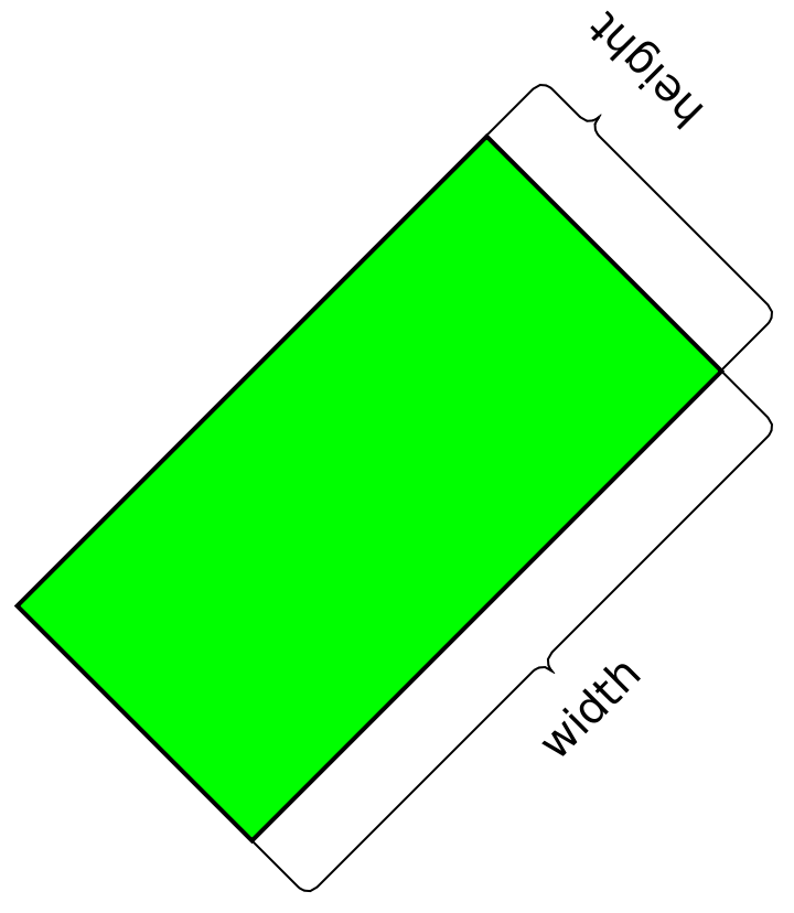
![obj = {Gray, Rectangle[{0, 0}, {1, .4}]};
Graphics[{{obj, ResourceFunction["GraphicsBrace"][
Style["width", 20], {0, 0}, {1, 0}], ResourceFunction["GraphicsBrace"][
Style["height", 20], {1, 0}, {1, .4}]}}]](https://www.wolframcloud.com/obj/resourcesystem/images/e32/e328f11a-ef17-41cc-860c-7ffec73a68f5/7505910588c10b23.png)

![obj = {RGBColor[0.5, 0.8, 0.12], Rectangle[{0, 0}, {1, .5}]};
Graphics[{{obj, ResourceFunction["GraphicsBrace"]["Underbrace", {0, 0}, {1, 0}], ResourceFunction["GraphicsBrace"]["Overbrace", {1, .5}, {0, .5}, RotateLabel -> False]}}]](https://www.wolframcloud.com/obj/resourcesystem/images/e32/e328f11a-ef17-41cc-860c-7ffec73a68f5/6a65e1253401a530.png)

![obj = {Orange, Rectangle[{0, 0}, {1, .4}]};
Graphics[{obj, ResourceFunction[
"GraphicsBrace"][{Style["width", 20], 0.1, 0.3}, {0, 0}, {1, 0}], ResourceFunction[
"GraphicsBrace"][{Style["height", 20], 0.3, 0.8}, {1, 0}, {1, .4}, RotateLabel -> False]}]](https://www.wolframcloud.com/obj/resourcesystem/images/e32/e328f11a-ef17-41cc-860c-7ffec73a68f5/3aa1f8e849aa50dc.png)

![obj = {Green, EdgeForm[Thick], Rotate[Rectangle[{0, 0}, {1, .5}], 45 Degree, {0, 0}]};
Graphics[{obj, ResourceFunction[
"GraphicsBrace"][{Style["width", 20]}, {0, 0}, {1/Sqrt[2], 1/Sqrt[
2]}], ResourceFunction[
"GraphicsBrace"][{Style["height", 20], 0.1, 0.8}, {1/Sqrt[2], 1/
Sqrt[2]}, {1/(2 Sqrt[2]), 3/(2 Sqrt[2])}, RotateLabel -> True]}]](https://www.wolframcloud.com/obj/resourcesystem/images/e32/e328f11a-ef17-41cc-860c-7ffec73a68f5/5a892da82ff053c0.png)
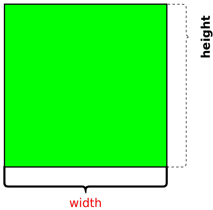
![obj = {Green, EdgeForm[Thick], Rectangle[{0, 0}, {1, 1}]};
Graphics[{obj,
{Thickness[0.01], ResourceFunction[
"GraphicsBrace"][{Style["width", 20, Red]}, {0, 0}, {1, 0}]},
{Dashed, ResourceFunction[
"GraphicsBrace"][{Style["height", 20, Bold], 0.1, 0.8}, {1, 0}, {1, 1}]}
}]](https://www.wolframcloud.com/obj/resourcesystem/images/e32/e328f11a-ef17-41cc-860c-7ffec73a68f5/28cdf1f7d5d08301.png)
![pt1 = Point[{0, 0.2}];
pt2 = Point[{0.8, 0.4}];
Graphics[{PointSize[0.02], pt1, pt2, ResourceFunction["GraphicsBrace"][Style["Point and Point", 20], pt1,
pt2]}]](https://www.wolframcloud.com/obj/resourcesystem/images/e32/e328f11a-ef17-41cc-860c-7ffec73a68f5/14cd686f159c9aa8.png)


![(* Evaluate this cell to get the example input *) CloudGet["https://www.wolframcloud.com/obj/b29fa0ef-a1d4-432f-b36e-e22e11e02cb2"]](https://www.wolframcloud.com/obj/resourcesystem/images/e32/e328f11a-ef17-41cc-860c-7ffec73a68f5/6b9f5448836ca193.png)
![(* Evaluate this cell to get the example input *) CloudGet["https://www.wolframcloud.com/obj/8c3be9a3-bd68-43f4-ab1b-d669cc863201"]](https://www.wolframcloud.com/obj/resourcesystem/images/e32/e328f11a-ef17-41cc-860c-7ffec73a68f5/216672420be65a9d.png)

![Graphics[{
ResourceFunction[
"GraphicsBrace"][{"Vertically offset label", {0., Offset[{0, -20}]}, .5}, {1.5, 0}, {2.5, 1}, RotateLabel -> False],
ResourceFunction[
"GraphicsBrace"][{"Horizontally offset label", {0., Offset[{-150, 0}]}, .5}, {3, 0}, {4, 1}, RotateLabel -> False]
}, ImageSize -> Large]](https://www.wolframcloud.com/obj/resourcesystem/images/e32/e328f11a-ef17-41cc-860c-7ffec73a68f5/64c41db766f80f46.png)

![(* Evaluate this cell to get the example input *) CloudGet["https://www.wolframcloud.com/obj/82b17bb6-eb61-42fc-93e9-afd7e9c55de1"]](https://www.wolframcloud.com/obj/resourcesystem/images/e32/e328f11a-ef17-41cc-860c-7ffec73a68f5/328c3e1acccb7fc2.png)

![Graphics[{
ResourceFunction["GraphicsBrace"]["No curve offset", {0, 0}, {1, 0},
0],
ResourceFunction["GraphicsBrace"][
"Curve offset equal to 1", {1.5, 0}, {2.5, 0}, 1],
ResourceFunction["GraphicsBrace"][
"Curve offset equal to 2", {3, 0}, {4, 0}, 2]
}]](https://www.wolframcloud.com/obj/resourcesystem/images/e32/e328f11a-ef17-41cc-860c-7ffec73a68f5/42b55223ac657905.png)

![(* Evaluate this cell to get the example input *) CloudGet["https://www.wolframcloud.com/obj/ce1a3e8b-084c-4711-aed7-e902f8709dee"]](https://www.wolframcloud.com/obj/resourcesystem/images/e32/e328f11a-ef17-41cc-860c-7ffec73a68f5/64e36263db3d9dc6.png)

![(* Evaluate this cell to get the example input *) CloudGet["https://www.wolframcloud.com/obj/b2146e8c-3c9c-4054-8d19-fd71a181027e"]](https://www.wolframcloud.com/obj/resourcesystem/images/e32/e328f11a-ef17-41cc-860c-7ffec73a68f5/4a9fd3f18d0d65cd.png)

![(* Evaluate this cell to get the example input *) CloudGet["https://www.wolframcloud.com/obj/1a76aef1-0069-4090-bd03-1e687e1b6165"]](https://www.wolframcloud.com/obj/resourcesystem/images/e32/e328f11a-ef17-41cc-860c-7ffec73a68f5/53a9668ce761916f.png)

![Graphics[{{Red, Dashed, Thick, ResourceFunction["GraphicsBrace"][
Style["Label", Bold, Blue, Italic, 40, Background -> Yellow], {0, 0}, {0, .3}]}}]](https://www.wolframcloud.com/obj/resourcesystem/images/e32/e328f11a-ef17-41cc-860c-7ffec73a68f5/3bc39e60afa60d2c.png)
![pt1 = {0, 0};
pt2 = {1, 1};
Graphics[{PointSize[0.05], Point[{pt1, pt2}], ResourceFunction["GraphicsBrace"] [
"Default setting", {0, 0}, {1, 1}]}, Axes -> True]](https://www.wolframcloud.com/obj/resourcesystem/images/e32/e328f11a-ef17-41cc-860c-7ffec73a68f5/7fa2006f5de013a0.png)
![Graphics[{PointSize[0.05], Point[{pt1, pt2}], ResourceFunction["GraphicsBrace"] ["Angle", {0, 0}, {1, 1}, Direction -> \[Pi]/8]}, Axes -> True]](https://www.wolframcloud.com/obj/resourcesystem/images/e32/e328f11a-ef17-41cc-860c-7ffec73a68f5/5b10c03cd99aa2e3.png)
![Graphics[{PointSize[0.05], Point[{pt1, pt2}], ResourceFunction["GraphicsBrace"] ["Vector", {0, 0}, {1, 1}, Direction -> {2.5, 1}]}, Axes -> True]](https://www.wolframcloud.com/obj/resourcesystem/images/e32/e328f11a-ef17-41cc-860c-7ffec73a68f5/027c6f9915573b1a.png)


![Graphics[{
ResourceFunction["GraphicsBrace"] ["Default radius", {0, 1}, {1, 1}],
ResourceFunction["GraphicsBrace"] [
"Larger radius", {0, 0.5}, {1, 0.5}, RoundingRadius -> 0.1],
ResourceFunction["GraphicsBrace"] ["Smaller radius", {0, 0}, {1, 0},
RoundingRadius -> 0.005]
}]](https://www.wolframcloud.com/obj/resourcesystem/images/e32/e328f11a-ef17-41cc-860c-7ffec73a68f5/072b0c5d7d7f315c.png)

![Graphics[ResourceFunction["GraphicsBrace"] [
"Outer radius = 0.15, inner radius = 0.05", {0, 1}, {1, 1}, RoundingRadius -> {0.15, 0.05}]]](https://www.wolframcloud.com/obj/resourcesystem/images/e32/e328f11a-ef17-41cc-860c-7ffec73a68f5/14b431dbc346b737.png)

![(* Evaluate this cell to get the example input *) CloudGet["https://www.wolframcloud.com/obj/adfc45ce-cdb9-4b2e-9de4-0d80315e3e46"]](https://www.wolframcloud.com/obj/resourcesystem/images/e32/e328f11a-ef17-41cc-860c-7ffec73a68f5/65acfb56294a2d47.png)

![Plot[f[x], {x, 0, 2}, PlotRange -> {All, {0, .7}},
Epilog -> {
ResourceFunction[
"GraphicsBrace"][{Style["increasing", Bold, 15], .05}, {argm, f[argm]}, {0, f[0]}, Direction -> \[Pi]/2, RotateLabel -> False],
ResourceFunction[
"GraphicsBrace"][{Style["decreasing", Bold, 15], .05}, {2, f[2]}, {argm, f[argm]}, Direction -> \[Pi]/2, RotateLabel -> False]
}, ImageSize -> Large]](https://www.wolframcloud.com/obj/resourcesystem/images/e32/e328f11a-ef17-41cc-860c-7ffec73a68f5/64cb8263ef606130.png)
![Graphics[{Text[Style["some text", 20], {0, 0}], ResourceFunction["GraphicsBrace"][
Nothing, {-0.05, -0.01}, {0.05, -0.01}, 0, RoundingRadius -> 0.01]}, ImageSize -> Tiny]](https://www.wolframcloud.com/obj/resourcesystem/images/e32/e328f11a-ef17-41cc-860c-7ffec73a68f5/3be675d6da976173.png)


![Graphics[{Thick, Table[With[{n = 5 s}, {ColorData[10][s], ResourceFunction["GraphicsBrace"][Nothing, ##, RoundingRadius -> .4] & @@@ Partition[N@CirclePoints[{0.3 n - 0.2, Boole@EvenQ@n}, n], 2, 1, {-1, 2}]}], {s, 3}]}, Background -> Lighter[Orange, 0.8]]](https://www.wolframcloud.com/obj/resourcesystem/images/e32/e328f11a-ef17-41cc-860c-7ffec73a68f5/416a2d54840d72af.png)
![pt1i = {0.06, -0.90};
pt2i = {-0.53, -0.05};
pt3i = {0.56, 0.90};
variableBrace[lab_, pt1_, pt2_, ang_ : Automatic] := ResourceFunction["GraphicsBrace"][
Style[ToString[Subscript["\[CapitalDelta]L", lab], TraditionalForm] <> " = " <> ToString[NumberForm[EuclideanDistance[pt1, pt2], 3]], 20], pt1, pt2, Direction -> ang, RoundingRadius -> .05]
Manipulate[Graphics[{Polygon[{pt1, pt2, pt3}],
variableBrace[1, pt1, pt3, dir],
variableBrace[2, pt3, pt2, dir],
variableBrace[3, pt2, pt1, dir]
}, PlotRange -> 1.],
{{pt1, pt1i}, Locator}, {{pt2, pt2i}, Locator}, {{pt3, pt3i}, Locator},
{{dir, Automatic, "Direction"}, {Automatic -> "Tangent", 0 -> "Fixed"}}]](https://www.wolframcloud.com/obj/resourcesystem/images/e32/e328f11a-ef17-41cc-860c-7ffec73a68f5/3e6253bf1e1f43dc.png)