Details and Options
ResourceFunction["CylindricalFlange3D"] can be used in
Graphics3D.
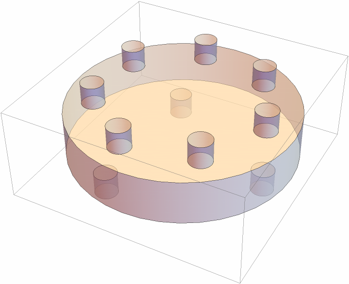
ResourceFunction["CylindricalFlange3D"] in general returns a (possibly large and nested) list of graphics primitives such as
Cylinder or
BSplineSurface that together constitute a flange.
ResourceFunction["CylindricalFlange3D"] is intended as a convenience function that allows for easy creation of composed cylinder-like graphics objects with textual labels. Its purpose is purely visual, no computation with the output (such as
RegionMeasure) is supported.
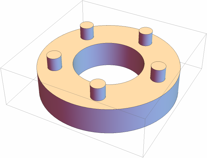
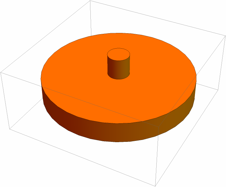
The first argument specifies the shape and size of the main graphics object, the other arguments specify the front and back protrusions and the protrusions along the circumference, respectively.
The first argument, type, can take any of the following forms:
| Automatic | default shape is set to "Cylinder" |
| shapename | string specifying the shape, see below |
| {shapename,length} | specify the length of the body (default is 0.4) |
| {shapename,length,rad} | specify the (outer) radius (default is 1) |
| {shapename,length,rad,pars} | specify additional parameters such as rounding radii (if any exist) |
Parameter shapename can take on the following forms:
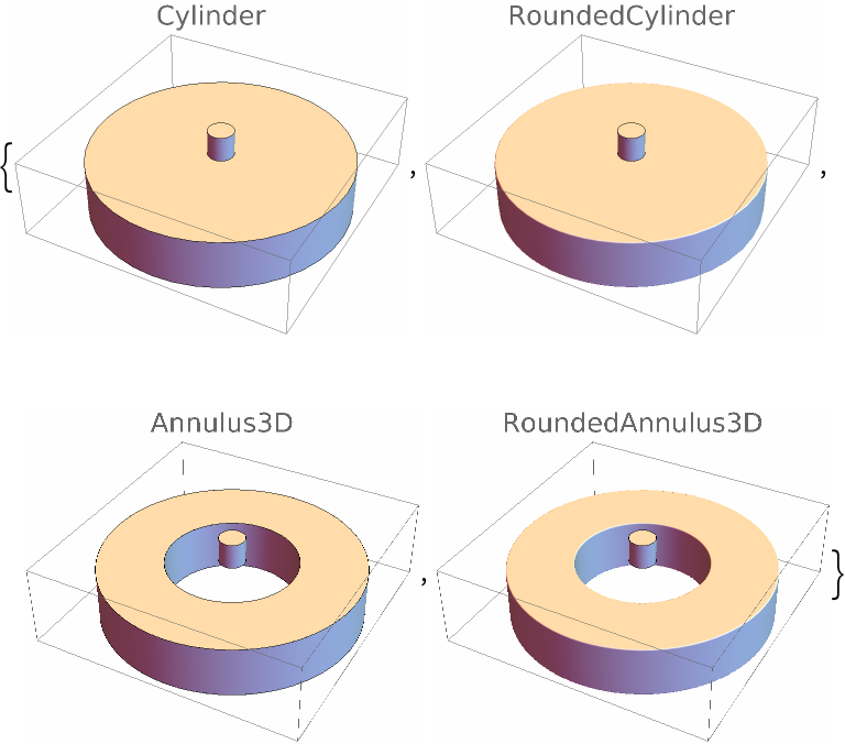
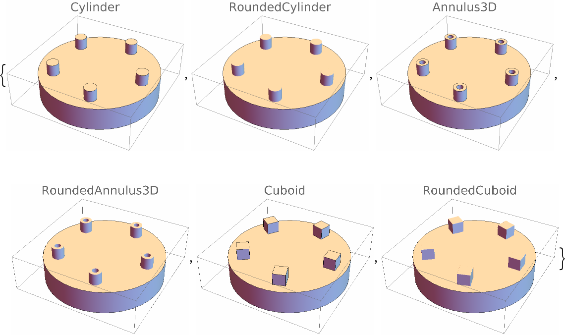
| "Annulus3D" | object given by ResourceFunction["Annulus3D"] |
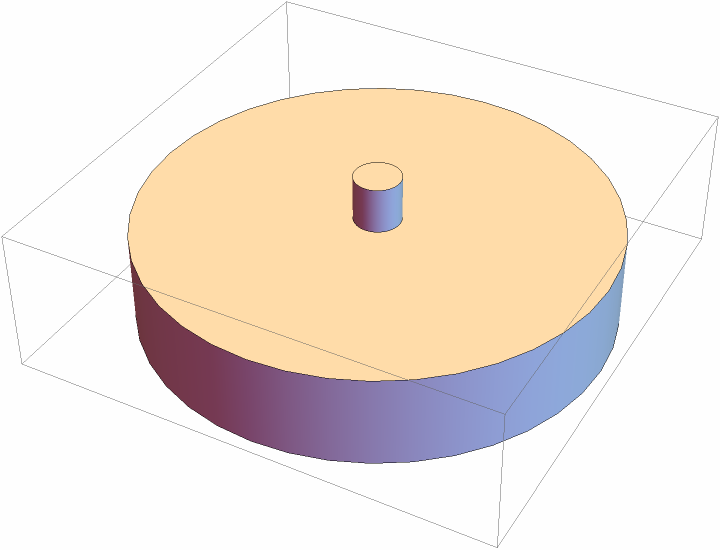
| "Cylinder" | object given by Cylinder |
| "Empty" | no object created |
| "RoundedAnnulus3D" | object given by ResourceFunction["RoundedAnnulus3D"] |
| "RoundedCylinder" | object given by ResourceFunction["RoundedCylinder"] |
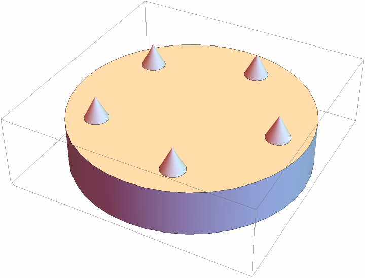
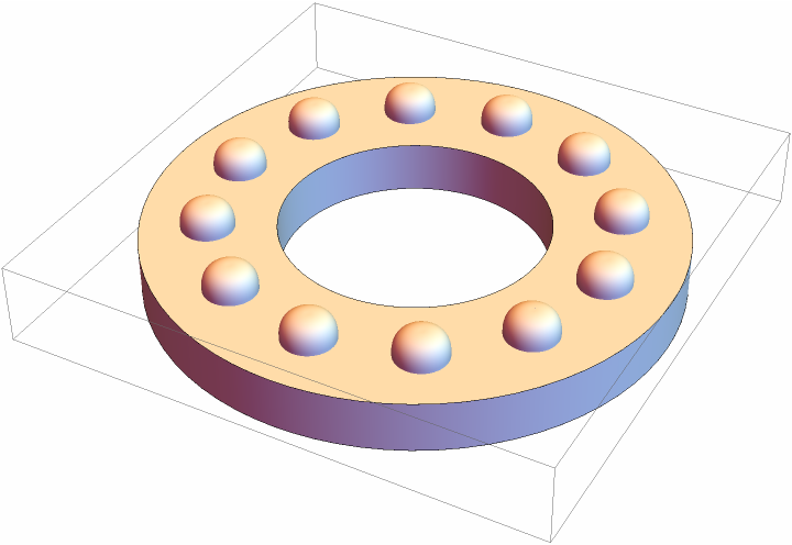
| fun[len,rad,pars] | object generated by a pure function |
For named shapes, the input parameters are checked for whether they lie in the allowed range. When a pure function is supplied instead, no parameter preprocessing is performed.
The second, third, and fourth arguments can be of the following forms:
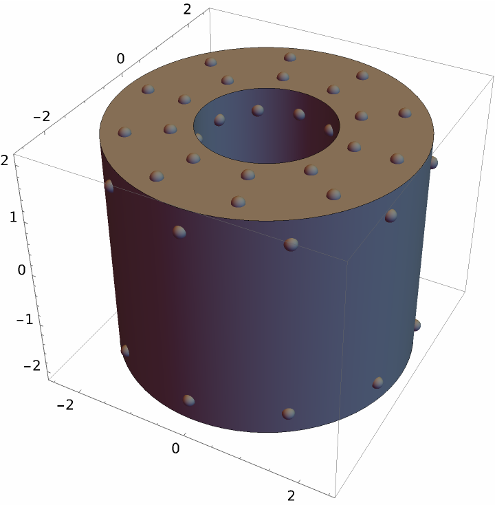
| num | integer number num of evenly distributed protrusions on a given face |
| posspec | list of protrusions' positions specified in the plane of the face (for front and back face) or along the surface of the circumference |
| {posspec,shapespec} | specify both the positions as well as the shape of the protrusions, see below |
The position specification posspec for protrusions can have the following forms:
| num | non-negative number of protrusions, evenly distributed on the face |
| {{rad1,th1},{rad2,th2},…} | list of polar coordinates for individual protrusions |
| {{rad1,th1,em1},{rad2,th2,em2},…} | together with the position also specify for each protrusion how much it should protrude from the surface |
The meaning of the polar coordinates is slightly different for front and back faces on the one hand, and for the circumference on the other hand. For the former, the first coordinate denotes a relative radial position of the protrusion on the face, while for the latter, the first coordinate specifies the relative position with respect to the center plane cutting through the main body. The meaning of the second and third coordinates is the same for all three faces. Namely, the second coordinate defines the angular position along the face and the third coordinate characterizes how much the protrusion sinks into the surface or protrudes from it.
The shape specification shapespec for protrusions follows exactly the shape specification for the main body. The allowed shapes are, however, slightly different:
The following full specifications for each shape are allowed:
| {"Cylinder",len,rad} | cylinder of length len and radius rad |
| {"Empty",len,rad} | empty cylinder-like object of given length and radius |
| {"Annulus3D",len,rad,inrad} | 3D annulus with inner radius inrad |
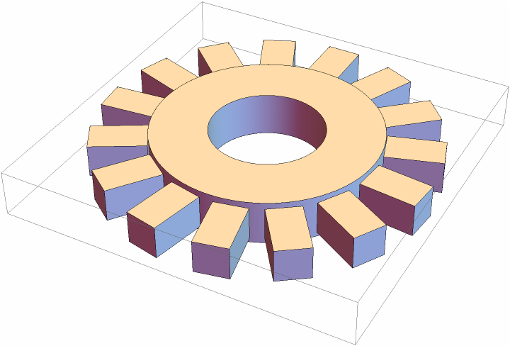
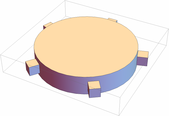
| {"Cuboid",z,hx,hy} | cuboid with length z, half-width hx, and half-depth hy |
| {"RoundedCylinder",len,rad,rrad} | rounded cylinder with rounding radius rrad |
| {"RoundedAnnulus3D",len,rad,inrad,rrad} | rounded 3D annulus with inner radius inrad and rounding radius rrad |
| {"RoundedCuboid",z,hx,hy,rrad} | rounded cuboid with rounding radius rrad |
When only a partial shape specification is given, default values are used instead. The default value for len is 0.4 for the main body and 0.2 for protrusions; for rad it is 1 for body and 0.1 for protrusions. Additional parameters are dynamically calculated from the values of these two parameters (if not supplied explicitly). The inner radius inrad and rounding radius rrad are set to 0.5rad and 0.01rad, respectively. For "Cuboid" and "RoundedCuboid" z is set to len, while hx and hy are set to rad.
The following options can be given:
| "Label" | None | textual label on the main object |
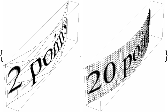
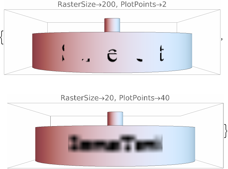
| PlotPoints | 20 | resolution of the cylindrical mesh underlying the label |
| RasterSize | 200 | raster size of each label |
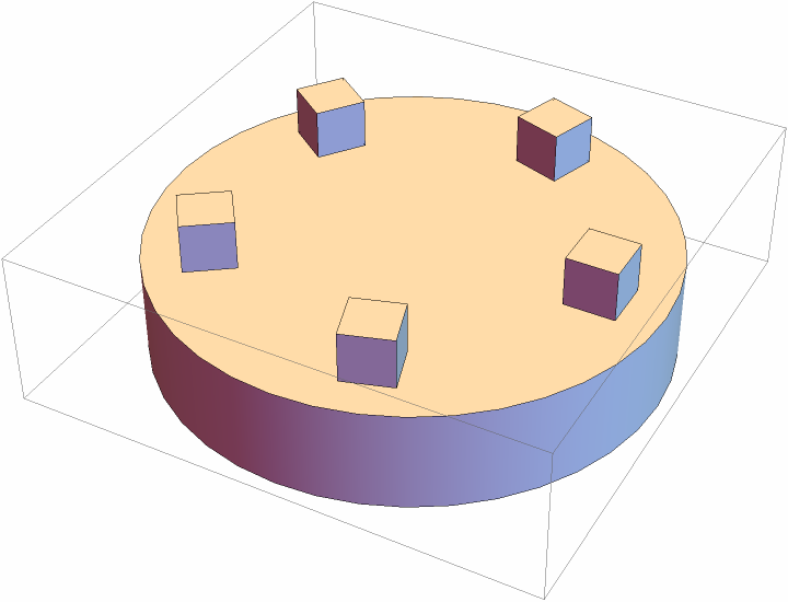
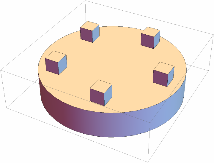
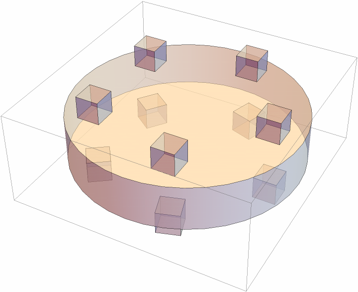
| "RotateProtrusions" | Automatic | whether to rotate the front and back protrusions |
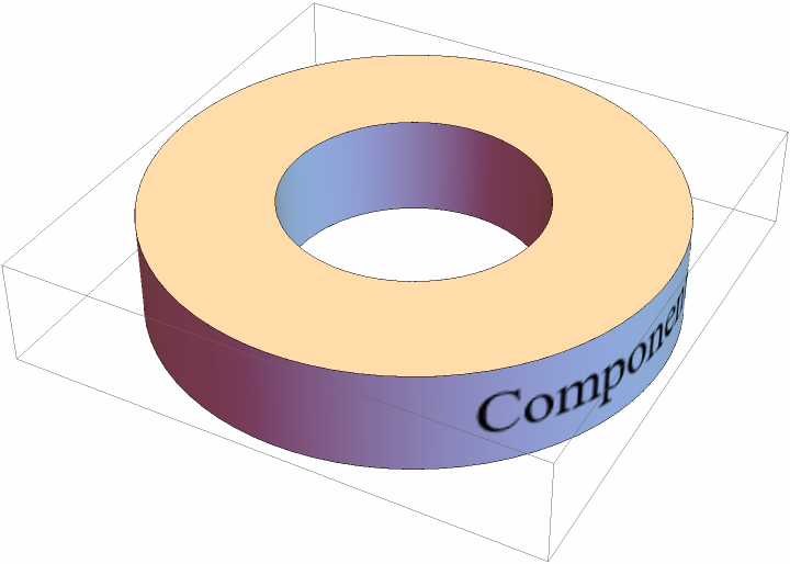
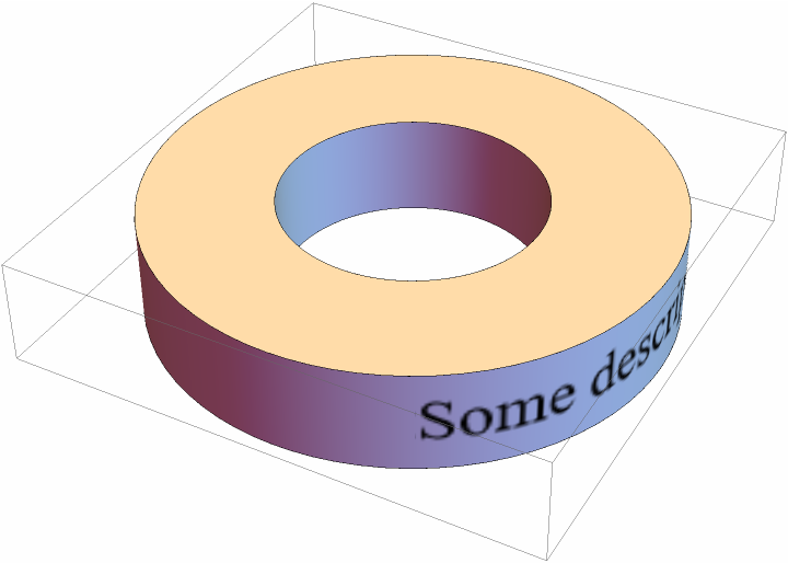
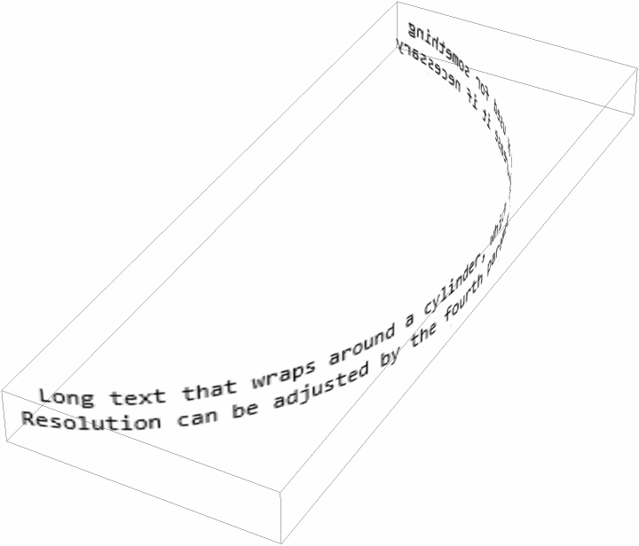
Textual labels specified by "Label" are represented as rasterized images wrapped in
Texture that spans a mesh created by
RevolutionPlot3D.
The "Label" setting can have the following forms:
| None | Automatic | no label |
| "SomeText…" | text of the label |
| Style[stylespec] | text wrapped in Style |
| {textspec,scale} | specify also a scale (default scale is 1) |
| {textspec,scale,orientation} | specify orientation (can be any real number, default is 0) |
The "RotateProtrusions" setting can have the following forms:
| True|False | specify whether the protrusions are rotated for both the front and the back face |
| Automatic | equivalent to False for types "Cylinder", "RoundedCylinder", "Annulus3D", and "RoundedAnnulus3D", and to True otherwise (default) |
| {frspec,bkspec} | specify individually for front and back face |
![Graphics3D[{ResourceFunction["CylindricalFlange3D"][
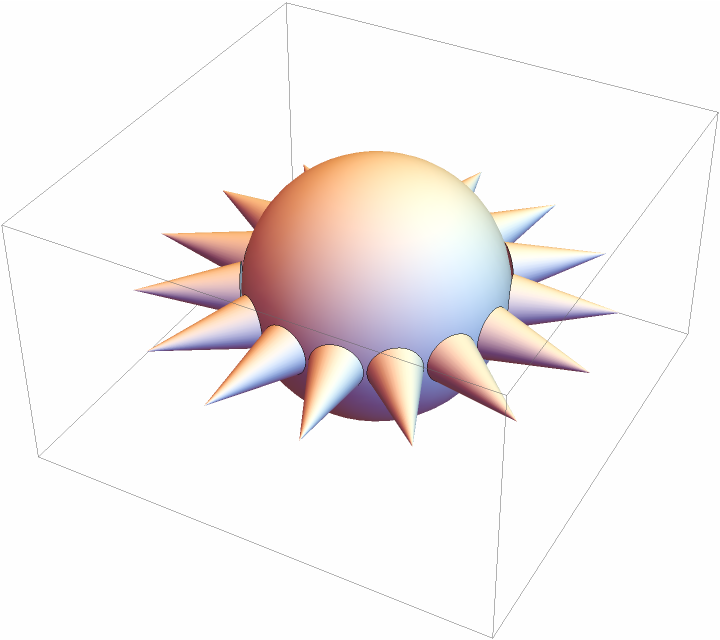
Ball[{0, 0, 0}, #2] &, 0, 0, {15, {Cone[{{0, 0, 0}, {0, 0, #1}}, #2] &, 0.8, 0.2, 0.15}}]}]](https://www.wolframcloud.com/obj/resourcesystem/images/c68/c6880bc5-602c-4102-9546-f23608e4efb9/6647d60e69d56a96.png)
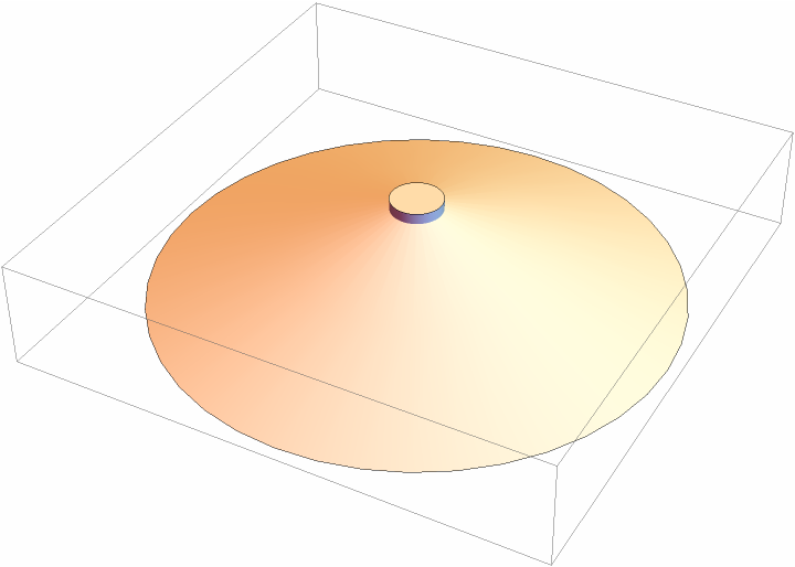
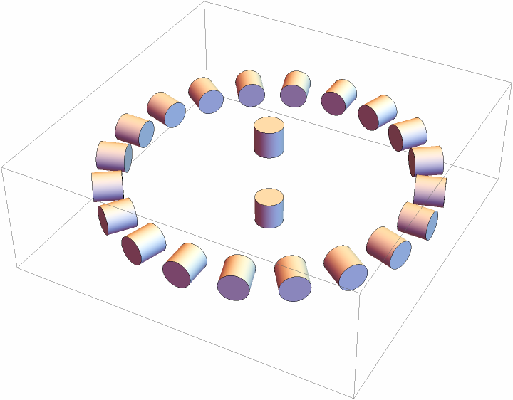
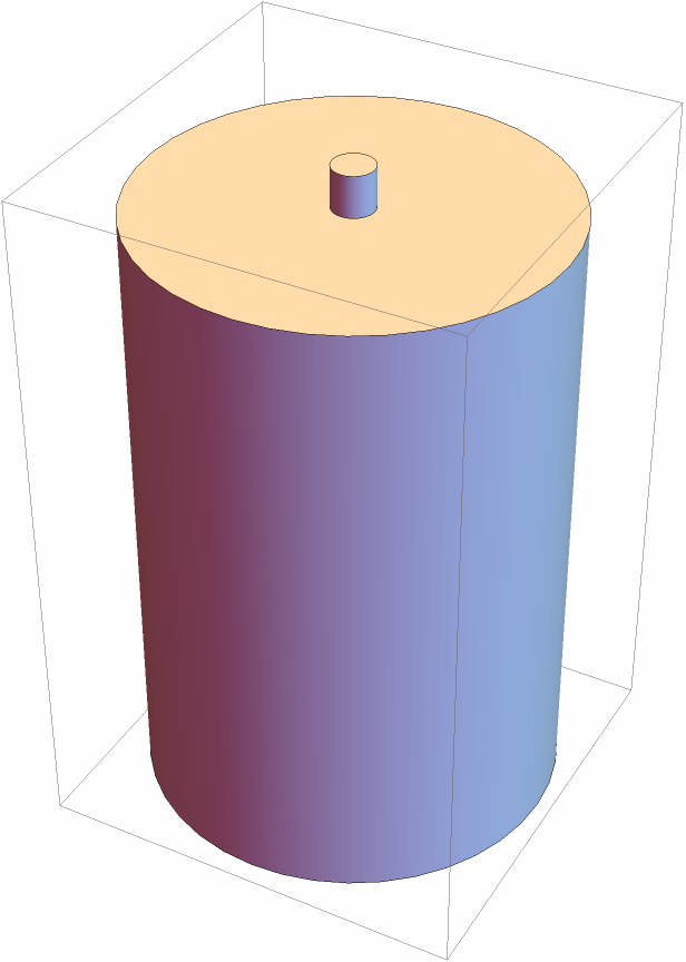
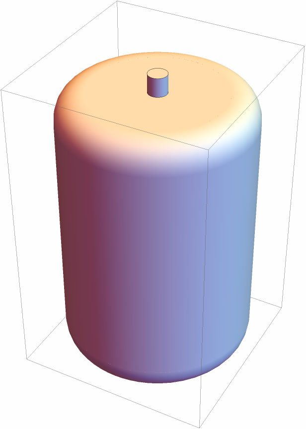
![{
Graphics3D[
ResourceFunction["CylindricalFlange3D"][
Automatic, {{1, 0}, {0, 0}, {-1, 0}}], PlotLabel -> "Different relative radii"],
Graphics3D[
ResourceFunction["CylindricalFlange3D"][
Automatic, {{1, 0}, {1, \[Pi]/4}, {1, \[Pi]/2}, {1, 3 \[Pi]/4}, {1,
4 \[Pi]/4}}], PlotLabel -> "Different angles"],
Graphics3D[
ResourceFunction["CylindricalFlange3D"][
Automatic, {{7/20, \[Pi]/8}, {9/20, \[Pi]/4}, {11/20, 3 \[Pi]/8}, {13/20, \[Pi]/2}, {3/4, 5 \[Pi]/8}}], PlotLabel -> "Different radii and angles"]
}](https://www.wolframcloud.com/obj/resourcesystem/images/c68/c6880bc5-602c-4102-9546-f23608e4efb9/12cb7883df9086be.png)

![Graphics3D[
ResourceFunction[
"CylindricalFlange3D"][{"Cylinder", 0.1, 1}, {{-1, 0, 0.1}, {-0.5, 0, 0.05}, {0, 0, 0}, {0.5, 0, -0.05}, {1,
0, -0.1}}], ViewPoint -> Front, ViewProjection -> "Orthographic"]](https://www.wolframcloud.com/obj/resourcesystem/images/c68/c6880bc5-602c-4102-9546-f23608e4efb9/4ec1b5f6d15f1c38.png)

![Graphics3D[ResourceFunction["CylindricalFlange3D"][Automatic, {5, #}],
PlotLabel -> #] & /@ {"Cylinder", "RoundedCylinder", "Annulus3D", "RoundedAnnulus3D", "Cuboid", "RoundedCuboid"}](https://www.wolframcloud.com/obj/resourcesystem/images/c68/c6880bc5-602c-4102-9546-f23608e4efb9/6019be30c832e5e4.png)
![Graphics3D[
ResourceFunction["CylindricalFlange3D"][
Automatic, {{{0, 0}, {0.8, \[Pi]/2}, {0.8, 3 \[Pi]/2}}, {"RoundedCylinder", 1, 0.2, 0.05}}]]](https://www.wolframcloud.com/obj/resourcesystem/images/c68/c6880bc5-602c-4102-9546-f23608e4efb9/6745e219cf7475c8.png)
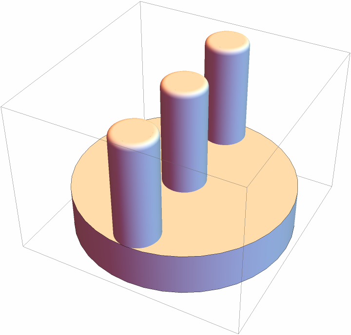
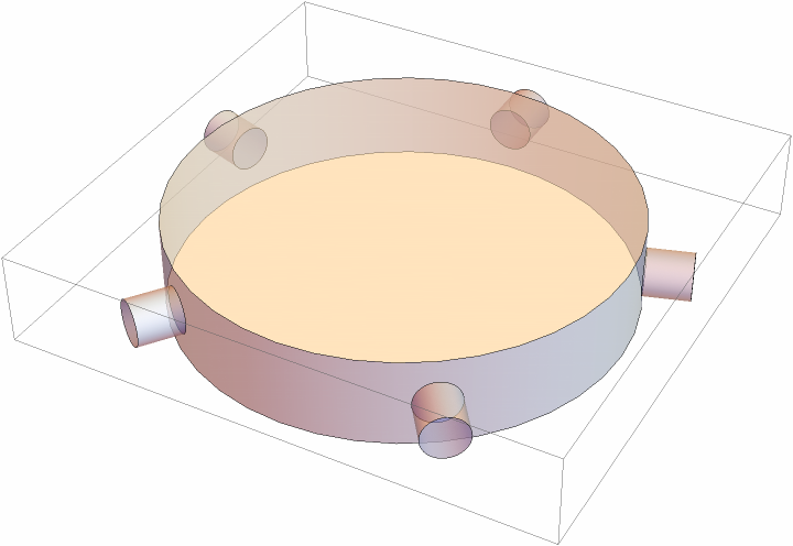
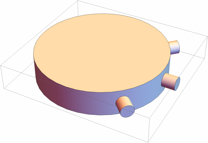
![Graphics3D[
ResourceFunction["CylindricalFlange3D"]["Cylinder", 0, 0, {{-1, \[Pi]/4}, {0, 2 \[Pi]/4}, {1, 3 \[Pi]/4}}], ViewPoint -> Left]](https://www.wolframcloud.com/obj/resourcesystem/images/c68/c6880bc5-602c-4102-9546-f23608e4efb9/073df974e47a2844.png)

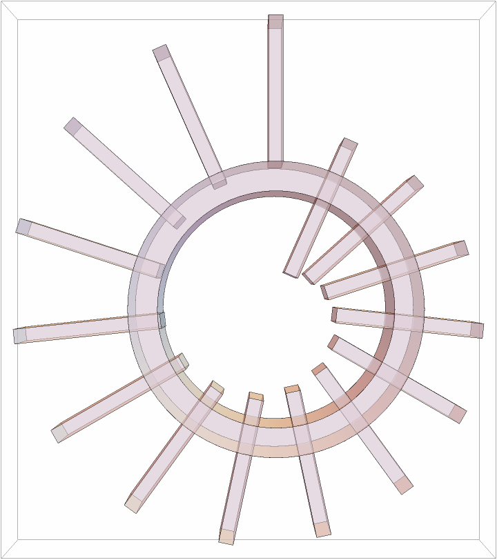
![coords = Table[{0, ang, -0.8 ang/(2 \[Pi])}, {ang, Most@Subdivide[0, 2 \[Pi], 15]}];
Graphics3D[{Opacity[0.5], ResourceFunction["CylindricalFlange3D"][{"Annulus3D", 0.5, 1, 0.8}, 0, 0, {coords, {"Cuboid", 1, 0.05, 0.2}}]}, ViewPoint -> Above]](https://www.wolframcloud.com/obj/resourcesystem/images/c68/c6880bc5-602c-4102-9546-f23608e4efb9/1667a13c951fdbb4.png)
![coords1 = Table[{0, ang, -.1}, {ang, Most@Subdivide[0, 2 \[Pi], 15]}];
coords2 = Table[{0, ang, -.55}, {ang, Most@Subdivide[0, 2 \[Pi], 15]}];
g1 = Graphics3D[{ResourceFunction[
"CylindricalFlange3D"][{"Annulus3D", 0.1, 1}, 0, 0, {coords1, {"Cuboid", 0.5, 0.05, 1}}]}];
g2 = Graphics3D[{ResourceFunction[
"CylindricalFlange3D"][{"Annulus3D", 0.5, 1, 0.8}, 0, 0, {coords2, {"Cuboid", 0.5, 0.05, 0.2}}]}];
g3 = Graphics3D[{ResourceFunction[
"CylindricalFlange3D"][{"Annulus3D", 0.5, 1, 0.8}, 0, 0, {coords2, {"Cuboid", 1, 0.05, 0.2}}]}];
{g1, g2, g3}](https://www.wolframcloud.com/obj/resourcesystem/images/c68/c6880bc5-602c-4102-9546-f23608e4efb9/1b8feea6d4399966.png)

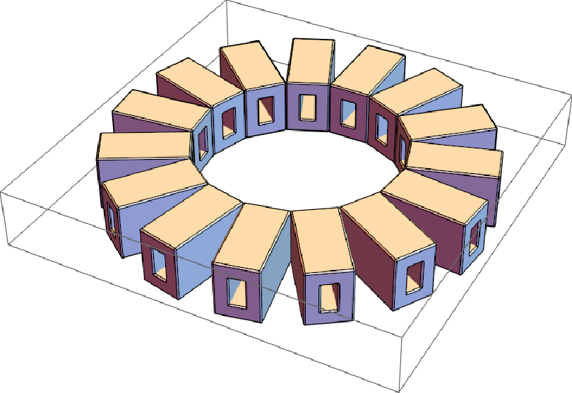
![funProtrusion[len_, rad_, pars___] := ResourceFunction["RoundedFrame3D"][{rad, pars[[1]], len}, {pars[[2]],
pars[[3]]}, RoundingRadius -> pars[[4]]]
Graphics3D[
ResourceFunction["CylindricalFlange3D"]["Empty", 0, 0, {15, {funProtrusion[##] &, 0.6, 0.3, {0.4, 0.1, 0.1, 0.01}}}]]](https://www.wolframcloud.com/obj/resourcesystem/images/c68/c6880bc5-602c-4102-9546-f23608e4efb9/20159c85fd693874.png)
![Graphics3D[{ResourceFunction["CylindricalFlange3D"]["Annulus3D", 0, 0,
0, "Label" -> Style[Column[{"Some text", "Second line"}, Alignment -> Center], FontColor -> Blue, FontFamily -> "Arial"]]}, ViewPoint -> Right]](https://www.wolframcloud.com/obj/resourcesystem/images/c68/c6880bc5-602c-4102-9546-f23608e4efb9/158e3c4e110daa11.png)

![Graphics3D[{ResourceFunction["CylindricalFlange3D"]["Annulus3D", 0, 0,
0, "Label" -> {"Some text", 0.2}]}, ViewPoint -> Right]](https://www.wolframcloud.com/obj/resourcesystem/images/c68/c6880bc5-602c-4102-9546-f23608e4efb9/47f932206e38fd4d.png)

![Graphics3D[{ResourceFunction["CylindricalFlange3D"]["Annulus3D", 0, 0,
0, "Label" -> {"Some text", 1, -\[Pi]/4}]}, ViewPoint -> Right]](https://www.wolframcloud.com/obj/resourcesystem/images/c68/c6880bc5-602c-4102-9546-f23608e4efb9/0491a2516323b35f.png)

![Graphics3D[{ResourceFunction["CylindricalFlange3D"]["Empty", 0, "Label" -> ToString[#] <> " points", PlotPoints -> #] /. _EdgeForm -> EdgeForm[Black]}] & /@ {2, 20}](https://www.wolframcloud.com/obj/resourcesystem/images/c68/c6880bc5-602c-4102-9546-f23608e4efb9/5e7e7816cebccf68.png)
![Graphics3D[
ResourceFunction["CylindricalFlange3D"][Automatic, "Label" -> "Some text", RasterSize -> 50], ViewPoint -> Right]](https://www.wolframcloud.com/obj/resourcesystem/images/c68/c6880bc5-602c-4102-9546-f23608e4efb9/45e82d838d9ba4f5.png)

![Graphics3D[{Opacity[0.5], ResourceFunction["CylindricalFlange3D"][
Automatic, {5, "Cuboid"}, {5, "Cuboid"}, "RotateProtrusions" -> {False, True}]}]](https://www.wolframcloud.com/obj/resourcesystem/images/c68/c6880bc5-602c-4102-9546-f23608e4efb9/5665f6f69dd2b7c8.png)
![ClearAll[specfun]
{len, rad, inrad} = {4, 2.5, 1.1};
specfun[x_, y_ : 0] := {Table[{x, ang, y}, {ang, Most@Subdivide[0, 2 \[Pi], 10]}], {Ball[{0, 0, 0}, #2] &, 0.1, 0.1, 0.09}};
Graphics3D[{Gray,
ResourceFunction[
"CylindricalFlange3D"][{"Annulus3D", len, rad, inrad}, specfun[0.85], 0, specfun[0.8]],
ResourceFunction["CylindricalFlange3D"][{"Empty", len, rad}, 0, specfun[0.85], specfun[-0.8]],
ResourceFunction["CylindricalFlange3D"][{"Empty", len, rad}, specfun[(inrad + 0.25 (rad - inrad))/rad], 0, specfun[0.8, -(rad - inrad)]],
ResourceFunction["CylindricalFlange3D"][{"Empty", len, rad}, 0, specfun[(inrad + 0.25 (rad - inrad))/rad], specfun[-0.8, -(rad - inrad)]]
}, Axes -> True]](https://www.wolframcloud.com/obj/resourcesystem/images/c68/c6880bc5-602c-4102-9546-f23608e4efb9/12b64ff8a5e21b6e.png)
![Graphics3D[{Lighter@Brown, ResourceFunction[
"CylindricalFlange3D"][{"Annulus3D", 0.01, 1, 0.6}, {1, {Ball[{0, 0, 0}, #2] &, 1, 0.5, 1}}]}]](https://www.wolframcloud.com/obj/resourcesystem/images/c68/c6880bc5-602c-4102-9546-f23608e4efb9/1bc497054d5241f4.png)
![Graphics3D[{Gray,
ResourceFunction[
"CylindricalFlange3D"][{"RoundedCylinder", 0.3, 2}, {7, {"RoundedCylinder", 0.8, 0.2}}, {1, {"RoundedCylinder", 2,
0.3}}],
Translate[Rotate[#, \[Pi]/2, {1, 0, 0}] &@
ResourceFunction[
"CylindricalFlange3D"][{"RoundedCylinder", 0.3, 2}, {7, {"RoundedCylinder", 0.8, 0.2}}, {1, {"RoundedCylinder", 4, 0.3}}], {0.4, 2, 2}]
}]](https://www.wolframcloud.com/obj/resourcesystem/images/c68/c6880bc5-602c-4102-9546-f23608e4efb9/793b18521d60e6c2.png)
![leaf = {Prism[{{0, 0, 0.2}, {0, 0, (0.2 + 3 #1)}, {0.6, 0, 0.2}, {0, 0.04, 0.2}, {0, 0.04, 3.2}, {0.6, 0.04, 0.2}}], Cylinder[{{0, 0, 0}, {0, 0, 0.6}}, 0.08]} &;
Graphics3D[{ResourceFunction[
"CylindricalFlange3D"][{"RoundedCylinder", 0.9, 0.5, 0.4}, 0, {{{0, 0, -0.1}}, {"Cylinder", 1, 0.3}}, {3, {leaf, 2, 0.3}}]}]](https://www.wolframcloud.com/obj/resourcesystem/images/c68/c6880bc5-602c-4102-9546-f23608e4efb9/3d93be639364e2bd.png)
![Graphics3D[{Orange, ResourceFunction[
"CylindricalFlange3D"][{"RoundedCylinder", 1, 2}, {1, {"RoundedAnnulus3D", 0.8, 1.8, 1.4}}, "Label" -> "Part no. 5 with some info", PlotPoints -> 60, RasterSize -> 300], Black, ResourceFunction[
"CylindricalFlange3D"][{"Empty", 1, 2}, {1, {"Cylinder", 0.5, 1.4}}], Orange, ResourceFunction[
"CylindricalFlange3D"][{"Empty", 1, 2}, {1, {"RoundedAnnulus3D", 0.8, 1.2, 1.0}}]}]](https://www.wolframcloud.com/obj/resourcesystem/images/c68/c6880bc5-602c-4102-9546-f23608e4efb9/70cb887b07458018.png)
![Graphics3D[{ResourceFunction["CylindricalFlange3D"]["Empty", 0, "Label" -> {Style[
Column[{"Long text that wraps around a cylinder, which could be used for something", "Resolution can be adjusted by the fourth parameter, increase it if necessary"}, Alignment -> Center]], 0.5}, RasterSize -> 500]}]](https://www.wolframcloud.com/obj/resourcesystem/images/c68/c6880bc5-602c-4102-9546-f23608e4efb9/5915b3dfacdb4aa7.png)
![{
Graphics3D[{ResourceFunction["CylindricalFlange3D"]["Cylinder", "Label" -> "SomeText", RasterSize -> 200, PlotPoints -> 2]}, PlotLabel -> "RasterSize\[Rule]200, PlotPoints\[Rule]2", ImageSize -> Medium, ViewPoint -> Right],
Graphics3D[{ResourceFunction["CylindricalFlange3D"]["Cylinder", "Label" -> "SomeText", RasterSize -> 20, PlotPoints -> 40]}, PlotLabel -> "RasterSize\[Rule]20, PlotPoints\[Rule]40", ImageSize -> Medium, ViewPoint -> Right]
}](https://www.wolframcloud.com/obj/resourcesystem/images/c68/c6880bc5-602c-4102-9546-f23608e4efb9/572c3e034cf91d7a.png)
![{
Graphics3D[{ResourceFunction["CylindricalFlange3D"]["Cylinder", "Label" -> {"SomeText", 1, 0}, RasterSize -> 200, PlotPoints -> 20]}, PlotLabel -> "RasterSize\[Rule]200, PlotPoints\[Rule]20", ImageSize -> Medium, ViewPoint -> Right],
Graphics3D[{ResourceFunction["CylindricalFlange3D"]["Cylinder", "Label" -> {"SomeText", 1, 0}, RasterSize -> 200, PlotPoints -> 40]}, PlotLabel -> "RasterSize\[Rule]200, PlotPoints\[Rule]40", ImageSize -> Medium, ViewPoint -> Right]
}](https://www.wolframcloud.com/obj/resourcesystem/images/c68/c6880bc5-602c-4102-9546-f23608e4efb9/629df170c6a79b6c.png)

![ClearAll[thorn]
thorn[len_, rad_] := Cone[{{0, 0, 0}, {0, 0, len}}, rad] &
Graphics3D[{ResourceFunction["CylindricalFlange3D"]["Annulus3D", 0, 0, {15, {thorn, 0.8, 0.1}}]}]](https://www.wolframcloud.com/obj/resourcesystem/images/c68/c6880bc5-602c-4102-9546-f23608e4efb9/45e7bc88fc80f41e.png)
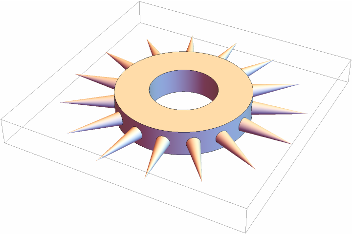
![ClearAll[thorn]
thorn = Cone[{{0, 0, 0}, {0, 0, #1}}, #2] &;
Graphics3D[{ResourceFunction["CylindricalFlange3D"]["Annulus3D", 0, 0, {15, {thorn, 0.8, 0.1}}]}]](https://www.wolframcloud.com/obj/resourcesystem/images/c68/c6880bc5-602c-4102-9546-f23608e4efb9/04a23f26ec5cfff6.png)
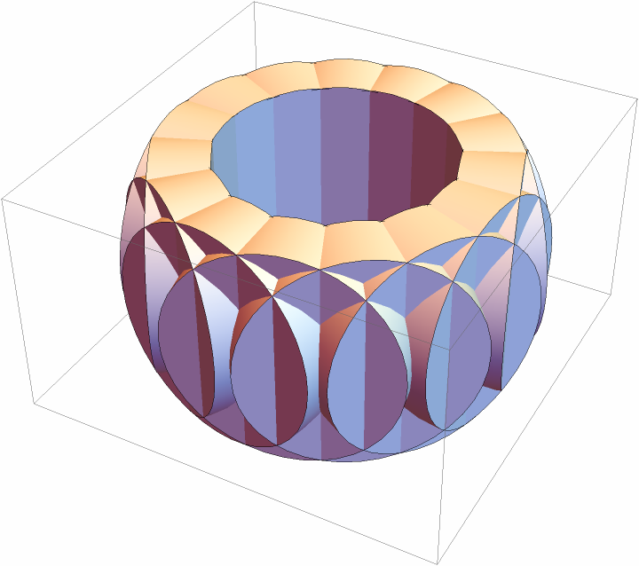
![Graphics3D[{ResourceFunction["CylindricalFlange3D"]["Empty", 0, 0, {15, {Cylinder[{{0, 0, 0}, {0, 0, #1}}] &, 0.5, 0.4, 0.15}}]}]](https://www.wolframcloud.com/obj/resourcesystem/images/c68/c6880bc5-602c-4102-9546-f23608e4efb9/4a8c33df4d8f46c6.png)
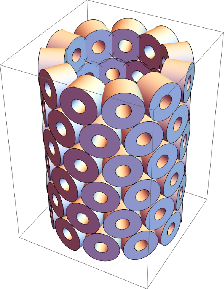
![gr = ResourceFunction["CylindricalFlange3D"]["Empty", 0, 0, {11, {"Annulus3D", 0.5, 0.4, 0.15}}];
gr2 = {gr, Translate[Rotate[gr, 0.3, {0, 0, 1}], {0, 0, 0.7}]};
Graphics3D[{Translate[gr2, {0, 0, 0}], Translate[gr2, {0, 0, 1.4}], Translate[gr2, {0, 0, 2 1.4}]}]](https://www.wolframcloud.com/obj/resourcesystem/images/c68/c6880bc5-602c-4102-9546-f23608e4efb9/1af4b79ebb131011.png)
![p1 = ResourceFunction[
"CylindricalFlange3D"][{"Annulus3D", 0.5, 2}, {8, {"Cylinder", 5, 0.3}}];
p2 = ResourceFunction[
"CylindricalFlange3D"][{"Cylinder", 0.5, 2}, {1, {"Cylinder", 1.2, 0.2}}];
p3 = ResourceFunction[
"CylindricalFlange3D"][{"Cylinder", 1.2}, {1, {"Cylinder", 3.4, 0.2}}, {1, {"Cylinder", 3, 0.2}}, {8, {"Cuboid", 0.5, 0.15, 0.4}}];
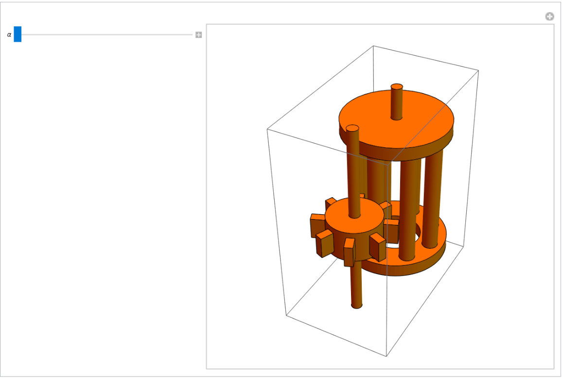
Manipulate[
Graphics3D[{Orange, Rotate[p1, \[Alpha], {0, 0, 1}], Translate[Rotate[p2, \[Alpha], {0, 0, 1}], {0, 0, 5.1}], Translate[
Rotate[p3, -\[Alpha] - 0.4, {0, 0, 1}], {0, -3, 2.5}]}], {\[Alpha], 0, 2 \[Pi]}]](https://www.wolframcloud.com/obj/resourcesystem/images/c68/c6880bc5-602c-4102-9546-f23608e4efb9/4ed35fd94868e6e1.png)
