Wolfram Language Paclet Repository
Community-contributed installable additions to the Wolfram Language
Circuit Diagram | |
"ShowWires" | True | whether to show horizontal wires |
"WireLabels" | Automatic | wire labeling |
"MeasurementWireLabel" | "c" | measurement wire label |
"MeasurementWirePosition" | Top | measurement wire position |
"ShowMeasurementWire" | True | whether to show a measurement wire |
"ShowEmptyWires" | True | whether to render empty wires |
"ShowExtraQudits" | False | whether to show non-positive ancillas |
"ShowLabel" | False | whether to include a circuit label |
"ShowGateLabels" | True | whether to show labels on gates |
"RotateGateLabel" | Automatic | rotation angle of gate labels |
"Size" | .75 | operator size |
"HorizontalGapSize" | 1 | distance between operators |
"VerticalGapSize" | 1 | distance between wires |
"GateBackgroundStyle" | Automatic | gate background style rules |
"GateBoundaryStyle" | Automatic | gate boundary style rules |
"GateShapeFunction" | Automatic | custom function to render gates |
"ShowOutline" | False | outline a circuit with a frame |
"ShowConnectors" | False | show points of wire-gate connections |
"ShowWireEndpoints" | False | show wire end-points |
"SubcircuitLevel" | 1 | level of subcircuits to expand up-to |
"SubcircuitOptions" | {} | pass additional diagram options to subcircuits |
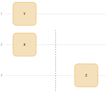
QuantumCircuitOperator |

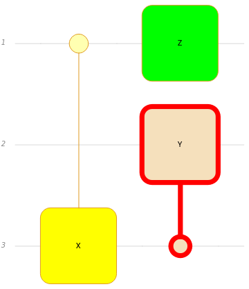
QuantumCircuitOperator |
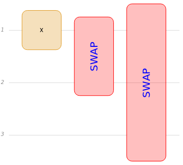
QuantumCircuitOperator |
QuantumCircuitOperator |

QuantumCircuitOperator |
QuantumCircuitOperator |
