This document presents a particular style of programming in Mathematica that allows the application of the Object-Oriented Programming (OOP) paradigm (to a point). The approach does not require the use of preliminary implementations, packages, or extra code. Using the OOP paradigm is achieved by following a specific programming style and conventions with native, fundamental programming constructs in Mathematica’s programming language.
We can say that the Object-oriented paradigm came to maturity with OOP Design Patterns, which were introduced in [5]. The book [5] describes Design Patterns as software architectural solutions obtained from analysis of successful software products. Design Patterns help overcome limitations of programming languages, give higher level abstractions for program design, and provide design transformation guidance. Because of extensive documentation and examples, Design Patterns help knowledge transfer and communication between developers. Because of these observations it is much better to emulate OOP in Mathematica through Design Patterns than through emulation of OOP objects.
It is beyond the scope of this document to give an OOP introduction to Design Patterns. For detailed description of the patterns implemented and discussed we are going to refer to [5]. (All of the design patterns considered in this document have entries in Wikipedia.)
The following Venn-like diagram shows the large context of patterns. This document is for the patterns in the dark red area (“Design Patterns by GoF”).
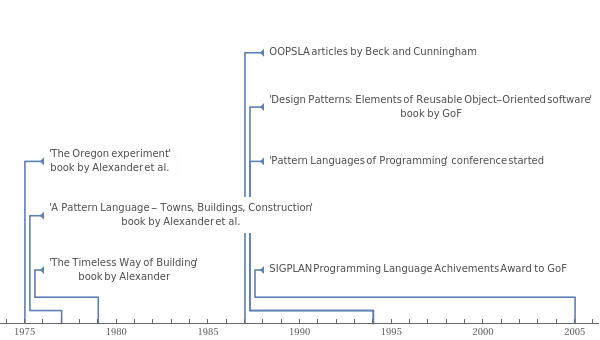
Design patterns history
In 1975 the architect Christopher Alexander et al., [2], introduced a pattern language for architectural solutions. Alexander’s book “The Timeless Way of Building”, [3], is the more fundamental one -- some sort of philosophical prequel of [1] and [2].
The computer scientists Kent Beck and Ward Cunningham started applying these ideas in software architecture in 1987 and presented results in the conference Object-Oriented Programming, Systems, Languages, and Applications (OOPSLA) -- see [4].
In 1995 the book by Gamma et al. “Design Patterns: Elements of Reusable Object-Oriented Software” provided a catalog of well researched and documented design patterns and that brought design patterns and pattern languages great popularity and acceptance. In 2005 ACM SIGPLAN awarded that year’s Programming Language Achievements Award to the authors. The authors are of often references ad the “Gang of Four” (GoF).
.
Design Patterns structure
The OOP Design Patterns in [5] are classified in three groups: creational, structural, and behavioral. The application of the structural and behavioral patterns in a design brings the need for the application creational patterns. In this document we are mostly interested in the structural and behavioral patterns, since in Mathematica creation of objects is much more immediate than in languages like C++ and Java.
The OOP Design Patterns are presented in a certain standard form. The form has four essential elements, [5], pattern name, problems for which the pattern is applicable, solution description, consequences of applying the pattern. The book [5] presents each pattern in the following form:
1
.
Pattern name and classification
2
.
Intent
3
.
Also known as
4
.
Motivation
5
.
Applicability
6
.
Structure
7
.
Participants
8
.
Collaborations
9
.
Consequences
10
.
Implementation
11
.
Sample code
12
.
Known uses
13
.
Related patterns
All enumerated parts are considered important.
(Because [5] is also structured as a manual it can be very difficult to read at first if the reader has little exposure to OOP. )
We are not going to follow the template given above. For each considered design pattern we are going to cite the intent from [5], provide code in Mathematica, and discuss applications inside Mathematica or with Mathematica.
Narration
It is accepted in technical and scientific writings to use plural voice or make neutral objective-like statements. Since Design Patterns were (and are) discovered in successful software that narrative style seems applicable. Understanding and applying Design Patterns, though, rely on extensive experience of software systems programming, maintaining, and utilization. Trying to apply them within a functional and rule based programming language like Mathematica inevitably requires a more personal perspective of programming and software goals.
Because of these observations I am going to use first person narration where objectivity cannot be fully guarantied, where there are multiple choices for the design solution, or where the design justification is based on past experience.
It seems appropriate at this point to discuss my past programming experiences.
Personal experiences with Design Patterns
This section is mostly to provide some background of why want to discuss the implementation of Design Patterns in Mathematica and why I think they are useful to apply in large development projects.
Large scale air-pollution modeling
In 2001 I obtained my Ph.D. in applied mathematics for writing an OOP framework for the numerical simulation of large scale air pollution (and writing related articles and thesis). Air pollution simulations over continents like Europe are grand challenge problems that encompass several scientific sub-cultures: computational fluid dynamics, computational chemistry, computational geometry, and parallel programming. I did not want to just a produce an OOP framework for addressing this problem -- I wanted to produce the best OOP framework for the set of adopted methods to solve these kind of problems.
One way to design such a framework is to use Design Patterns and did so using C++. Because I wanted to bring sound arguments during my Ph.D. defense that I derived on of the best possible designs, I had to use some formal method for judging the designs made with Design Patterns. I introduced the relational algebra of the Database theory into the OOP Design Patterns, and I was able to come up with some sort of proof why the framework written is designed well. More practically this was proven by developing, running, and obtaining results with different numerical methods for the air-pollution problems.
In my Ph.D. thesis I showed how to prove that Design Patterns provide robust code construction through the theory Relational Databases, [13].
(One of the key concepts and goals in OOP is reuse. In OOP when developing software we do not want changes in one functional part to bring domino effect changes in other parts. Design Patterns help with that. Relational Databases were developed with similar goals in mind -- we want the data changes to be confined to only one relevant place. We can view OOP code as a database, the signatures of the functions being the identifiers and the function bodies being the data. If we bring that code-database into a third normal form we are going to achieve the stability in respect to changes desired in OOP. We can interpret the individual Design Patterns as bringing the code into such third normal forms for the satisfaction of different types of anticipated code changes.)
While working at Wolfram Research Inc. I re-implemented that framework in order to demonstrate the capabilities of
grid
Mathematica
. (And that demo became quite popular and presented in different conferences in 2006 and 2007.) The re-implementation in top-level Mathematica code was done using Design Patterns, [6].
Numerical integration
After joining Wolfram Research, Inc. I designed, developed, and documented the (large) numerical integration framework of
. The implementation was done using both C and Mathematica and I used Design Patterns with both languages.
Other applications
In the last 9 years I have worked in the field of machine learning and data mining. I have used Design Patterns to implement digital media search engines, recommendation engines, and a broadcast scheduler. I use Design Patterns when I program larger projects in Mathematica or R and I always use Design Patterns when I program in Java and C++.
” in Mathematica StackExchange, I realized that the problem and desired functionalities presented there are both complex enough and simple enough to make a good example of object-oriented implementation in Mathematica using Design Patterns. The package
(UML) diagrams used in this document are more basic than the ones used in [5], but provide (I hope) a sufficient visual aid. They are generated over the Mathematica implementation code of the Design Patterns. See the package
In UML abstract classes and operations (methods) are given in slanted font (italic). Inheritance is depicted with a line with unfilled triangle pointing to the parent class.
Here is a list of notions I assume the readers of this document to be familiar with:
◼
S-expressions
◼
Closures
◼
Dynamic and lexical scoping
◼
Inheritance & Delegation
◼
DownValues, SubValues
Class inheritance
Inheritance is the fundamental implementation to understand. This section shows delegation to a more abstract class. The section “Template Method” shows how to make the ancestor delegation even more useful.
Consider the following example. We have three classes C0, C1, and C2. The class C1 inherits C0, C2 inherits C1. We write this as C0←C1←C2.
UML diagram
Implementation
The basic idea is to use symbols` sub-values.
Experiments
Here we define a C2 object:
This invokes C1' s definition
This invokes C2's definition:
Finally, this invokes C0’s definition:
Let us look into more detail of what is happening. We have made an object of the class C2, meaning we have an expression with head C2 and some data inside the expression:
There are sub-value rules for C2:
Here is one more example:
It is instructive to look at the evaluation trace of C2 and C1 expressions called over “f1”. For example:
Static class inheritance
The inheritance implementation in the previous section was achieved through dynamic resolution of the symbols sub-value rules in order to invoke the corresponding implementation for a given signature. We can implement static inheritance by using direct manipulation of sub-values.
The idea of the static inheritance is simple: (i) we take the sub-values of the parent and assign them to the child, and (ii) we change one or several of child sub-values to correspond to the desired changes of behavior.
Note that the classes have the same definitions of the “delegated” function members. Using static inheritance we have saved copying and assigning code.
UML diagram
Implementation
Static inheritance C0 C1:
Static inheritance C1 C2:
pos is for the positions of the overridden methods.
Experiments
Here we define a C2 object:
Functions borrowed from C0:
Functions borrowed from C1:
And finally genuine the C2 function:
It is instructional to see the definitions of the symbols defined above.
Global`C0
Template Method
Define the skeleton of an algorithm in an operation, deferring some steps to subclasses. Template Method lets subclasses redefine certain steps of an algorithm without changing the algorithm’s structure.
Motivational example
Mathematica has the function Inner that perfectly demonstrates the usefulness of Template-Method-like functionality code breakdown.
Here is an algorithm “skeleton” made with Inner:
We can easily derive different algorithms by replacing the symbols op1 and op2 with concrete functions:
Alternatively, we can consider varying the data arguments of Inner:
These concrete implementations of op1 and op2 provide different functionalities depending on the data types:
Note that for _Mat objects the code above returns the result in MatrixForm.
UML diagram
Implementation
For the implementation of Template Method we basically combine sub-values with Block's dynamic scoping.
Experiments
It is instructive to see the trace of the invocations.
This call uses a method defined in the abstract class:
This trace shows the call for the abstract algorithm (template method) for a concrete class object that invokes the primitive operation defined in that concrete class.
Other concrete examples
Template Method version of the motivational example
Using the motivational example let us implement a class hierarchy adhering to the Template Method that provides an invariant algorithm and different specializations of its concrete operations.
Note that there is the question of the right selection of a Template Method descendant for a given pair of argument objects. There are creational Design Patterns that address these type of problems (Abstract Factory, Factory Method); see [5]. In Mathematica we can easily address that problem with pattern matching.
GitHubData
The functionality of the main GitHub data class in [5] GitHubData is modified with the descendant object GitHubDataMessageHyperlinks so the ticks of the plots have hyperlinks to the github.com pages corresponding to the commits. The template method algorithm is the method “Plot”, the primitive operations are “ParseData”, “TickLabels”, and “DatePoints”. The class GitHubDataMessageHyperlinks provides its own implementation of “TickLabels” (making the ticks click-able).
Strategy
Here is intent of the design pattern Strategy from [5]:
Define a family of algorithms, encapsulate each one, and make them interchangeable. Strategy lets the algorithm vary independently from clients that use it.
Generally Strategy’s structure is not needed in Mathematica because of the functional programming paradigm support and pattern matching of function signatures. Conceptually Strategy is applied all the time, e.g. second order functions or writing functions with arguments being other functions.
Nevertheless, we are going to give an implementation of Strategy that might be useful when prototyping in Mathematica and considering moving to production languages like C++ or Java. The implementation is essentially similar to the one given in the section “Inheritance”. Here we are going to endow it with additional code to facilitate the use of the class hierarchy within several Design Patterns.
UML diagram
Implementation
Experiments
Here we create an object of StrategyContext using a concrete strategy object:
Here we simply replace one concrete strategy with another concrete strategy:
Uses in Mathematica
As it was mentioned above all second order functions (Map, Fold, Nest, FixedPoint, etc.) provide good examples of the functionality achieved by Strategy. Further, very often the algorithms specified by the Method option in different functions can be seen -- at least conceptually -- as playing within the Strategy design pattern.
Other concrete examples
The plotting functionality of the main GitHub data class in [5] GitHubData given by the method “Plot” is changed through the Strategy design pattern. The data member “PlotFunction” can be set to one of the functions GHDDateListPlot, GHDBarPlot, or GHDGraphics3D. In this way different plots are derived for the representation of the ingested GitHub data.
Composite
Compose objects into tree structures to represent part-whole hierarchies. Composite lets clients treat individual objects and compositions of objects uniformly.
A typical example is moving one or several desktop icons by mouse selection and dragging.
UML diagram
Implementation
Experiments
First we create concrete non-composite Component objects (leafs).
Next we create a composite object and add the leaf objects to it.
Here is code creating and operating a second composite object that uses the first composite object:
Other concrete examples
The GitHubData object utilizes Composite to visualize the commit histories of a collection of GitHub repositories.
Decorator
Attach additional responsibilities to an object dynamically. Decorators provide a flexible alternative to sub-classing for extending functionality.
A typical example is adding scroll-bars to screen outputs.
Motivational example
Here is a core algorithm that takes randomly a specified number of words from a text:
CoreAlg might give a very large output, so we want to confine its output in a small window and use scroll-bars to examine the content:
Further, we might want to show in red certain special words:
UML diagram
Implementation
Experiments
First we create concrete components.
Next we create concrete decorators that wrap around the component objects.
Other concrete examples
In [6] Decorator was used to implement a Single Instruction Multiple Data (SIMD) parallel algorithm for handling the simulations.
GitHubData objects use Decorator for changing of the font styles and the colors of graphs and charts. See [8].
Observer
The design pattern Observer is also known as Model-View-Controller (MVC).
The MVC functionality within Mathematica
Here is a slightly modified version an example from the function page for Dynamic:
The example above allows to change the value in the input field by moving the arrow, and change arrow's direction by changing the input value. (This MVC behavior is similar in spirit to the one in the motivational example for Observer in [5].)
UML diagram
For Observer it is beneficial to see not just an structural UML diagram but also an UML interaction sequence diagram, see[5]. Here is shown just a structural one.
Implementation
Experiments
First let us we create a concrete subject to be observed.
The signature of the creating function is such that it has the head of the concrete subject class ConcreteSubject and it takes two arguments, an identifier symbol and a list of observers (that can be empty). The creator function returns a ConcreteSubject object.
Next we are going to set a state for the concrete subject.
Let us create two concrete Observer objects, one for printing the state of the subject, the other for plotting the state of the subject.
What the creator functions of the observers do parallels what the creator for concrete subject objects does. The signature of each creating function is such that it has the head of the concrete observer class and it takes two arguments, an identifier symbol and a list of subjects (that can be empty). The creator functions return the corresponding concrete observer objects.
Next we attach the observers to the subject.
This command retrieves the current state of the subject:
The following command notifies the observers attached to the subject about its state. The result is a list of the observers views on the subject’s state.
Let us change the state of the subject to something else.
And let us notify the attached observers to react to the state change.
Interpreter
Given a language, define a representation for its grammar along with an interpreter that uses the representation to interpret sentences in the language.
Interpreter is a powerful design pattern that allows to approach the solution of re-occurring problems using Domain Specific Languages (DSL’s).
UML diagram
Backus-Naur Form (BNF)
Here is the BNF of a DSL for handling Boolean expressions of a certain type:
The implementation follows the BNF in the previous section.
Dummy client class for the UML diagram.
Experiments
(true and x) or (y and (not x))
Other concrete examples
I designed and implemented NIntegrate’s Method option using the Interpreter design pattern. (That design was also applied to NSum.) See [9] for brief details.
Extension
For example here is the Extended BNF (EBNF) of a simple grammar for expressing food desires:
This command generates the grammar parsers:
These commands show the parsing of different sentences of the grammar defined above:
At this point it is easy enough to develop interpreters for the parsed sentences.
Future plans
1. Implement the generation of UML object interaction sequence diagrams using Design Patterns implementations (in Mathematica).
2. Implement code generation based on specified Design Patterns. It is especially interesting the code generation to be specified by natural language sentences describing the system architecture.
3. Investigate discovering design patterns within existing code.
References
[1] Christopher Alexander et al., The Oregon Experiment, Oxford University Press, 1975.
[2] Christopher Alexander et al., A Pattern Language - Towns, Buildings, Construction, Oxford University Press, 1977.
[3] Christopher Alexander, The Timeless Way of Building, Oxford University Press, 1979.
[4] Kent Beck, Ward Cunningham, “Using Pattern Languages for Object-Oriented Programs”, OOPSLA-87, (1987).
[5] Erich Gamma, Richard Helm, Ralph Johnson, John Vlissides, Design Patterns: Elements of Reusable Object-Oriented Software, Addison-Wesley, 1994.
[13] Anton Antonov, Object-oriented framework for large scale air pollution models, 2001. Ph.D. thesis, Informatics and Mathematical Modelling, Technical University of Denmark, DTU.